 |
This
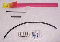
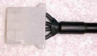
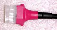
tutorial is designed to show you how to fabricate connectors such as the one you
see here. The materials used are simple and widely available from most local and
internet-based vendors. I make use of microphone cabling in this application
mainly due to it's pleasing appearance and flexibility. There are normally two
conductors and a single shield that works out perfectly for Molex power
connection since there is actually only three copper paths used in this
application: Ground, +12v, and +5v. Below I plan to show you how to fabricate
these connectors yourself... |
 |
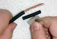
Be sure to remember to slip on your heatshrink you're
going to be using before
ever getting started!! What usually helps me is to visualize in my head
the sequence of parts I'm going to be using so that I don't miss something
when it's too late. |
|
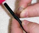
Make the cut and remove the outer insulation. As you can
see, I like using a razor blade for this cut but there are plenty of
excellent wire stripping tools out there and work very well. I'm just too
cheap to go that route! |
 |
 |
 |
 |
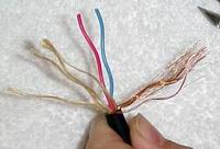
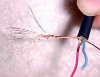
Separate the different strands and remove any filler.
Split the shield into two groups. |
|
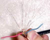
Flare out the strands of the unshielded wires and twist them tightly. This will help them hold their shape until you apply the heatshrink. |
 |
 |
 |
 |
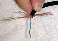
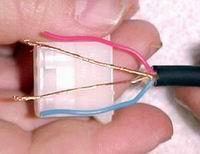
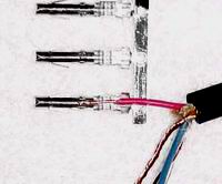
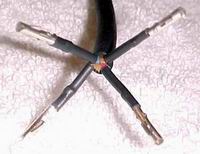
Arrange the wires as shown. If you do have a red wire, place it opposite of the ridge as shown. This will keep it in line with the present standard wiring scheme. Red is for +5v and the opposite is for +12v (normally yellow). The center exposed wires replace the normally black ground wires. The nice thing is that the ground wires shield this cable until it terminates at the connector! |
|
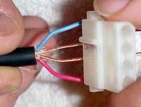
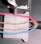
Trim the wires as shown. I like to go along the horizontal ridge of the connector as you can see. The object is to wind up with enough bare wire to be able to fold over the area that will eventually be crimped inside the pin. |
 |
 |
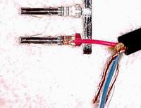 |
Strip the insulated wires and fold over as shown. There are two crimp points in these pins. One is for the conductor and the other is to grip the insulation. I like to fold over the exposed wire to improve the contact area. |
|
Crimp the pins as shown. You can find the crimping tool at Jameco listed along with the pins. I think it is less than $10. |
 |
 |
 |
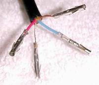
Cut and install heatshrink to the individual wires as shown. I like to run the heatshrink right up to the crimp point as this helps keep the pins centered in the connector once installed. |
|
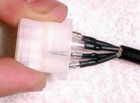
Insert the pins in the connector. I strongly suggest inserting them all at the same time! Be sure to keep the red wire opposite of the ridge as shown above. |
 |
 |
 |
 |
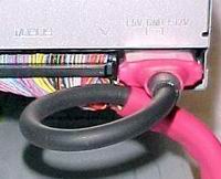
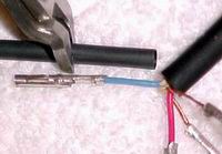
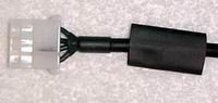
Slip on your first heatshrink piece for the entire cable and shrink it down. The heatshrink I use has a small amount of heat-activated adhesive that helps in this case keep the smaller wires in place at the end (as I'm sure you can see). |
|
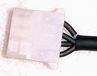
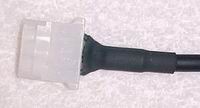
I use a second piece of heatshrink in these applications as it helps the final red piece grip on the cable correctly. |
 |
 |
 |
 |
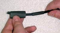
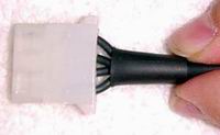
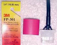
Install the final heatshrink piece. It's about an inch in length and barely fits over the Molex connector before heating. |
|